This is a work in progress but as the blog is being written at the same time as I am working (for a change), I thought I might as well publish it to make it a live update of sorts. So do pop back in the future to see when I finally give up and set the lot on fire.
I can see this one growing some legs so I am separating it from the wiring thread to give it space of its own.
My alternator had 3 main issues, It didn't appear to be pumping out any power, the wiring looked a bit crispy, as did the rear case of the alternator itself.
What is it
After a bit of looking about, it appears to be a Lucas 18ACR which was factory fit with the Xflow motors. Copies of these can be picked up for £53 so no great expense there and well worth just replacing on speck. I also bought a euro plug for reasons that would be clear later. I also bought a new engine earth strap (you can just make it out in the background of fig1.1. It was a bit frayed and looked like a weak point.
 |
| fig1.1 |
Crispiness
The melted wires and rear casing were all linked to the location of the alternator, tucked up under the exhaust manifold. A heat shield would be a simple way of preventing this issue from continuing which will be coming soon.
I will make a heat shield in due course but for now, left over heat shield from the boot lid was used to protect the new generator and a healthy amount of fire proof wiring sleeve was used for the wires. To further protect items in the engine bay from exhaust heat, the exhaust manifold was removed, cleaned, wrapped and reinstalled with fresh gaskets as in fig 2.1.
*Insert fig*
The wires
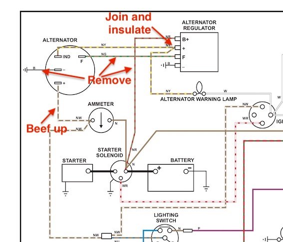
Crispiness aside, the wiring had some more issues. I didn't have to look hard to see that there was some alternative wiring going on here. Unfortunately, I am still not 100% sure what car the wiring loom is out of but the alternator part of the loom tends to be pretty similar between different brands. A trip to Google showed me a great post discussing the various wiring found on different generations of alternators and how to wire each. The two-pin outlet of my current 18ACR had a thin brown on the indicating terminal, one output going to the radiator water temp sensor via the red wire and the brown and yellow on the other. It looks like what I have is wired like a three-pin but to a two-pin connector with an additional accessory. Very confusing. In fact, looking at the wiring on a Lucas 18ACR as used on a TR7 you could see how you could get confused and wire this incorrectly. Either way it explains why it doesn't work.
Identifying wires
As can be seen in fig1.1 the thick brown and yellow that I'd expect to be connected to the alternator has been cut. In theory, reconnecting that, disconnecting the brown wire and moving the indicating line to the correct terminal would get us to the correct wiring for a 2-pin alternator. Of course that is wrong and I will get to that later.
The rogue red is in actual fact an accessory. It is used to power the twin radiator fans and is switched by a thermostat on the radiator. It is individually fused and completely separate from the ignition so it can cool the water even when the engine is switched off. This is the one wire that appears to be correct if a bit skinny for its intended purpose.
A bit of pondering later and I had thing sussed out. The wiring had been simplified from whatever loom had been used to build the car only using the thick brown for power leaving the accessory brown and yellow disused (hence cut) allowing the red line to be connected for cooling.
The reason the alternator would not work is that there was no ignition light in the car. This is needed as it runs a battery positive to the alternator (through the thin brown and yellow line) giving a current to induce charging when the generator is spinning.
https://www.youtube.com/watch?v=Y0FjQzMYuJI&pp=ygUWYmVuY2ggdGVzdCBhbHRlcm5hdG9yIA%3D%3D
This video was helpful in explaining how this works and helps to identify if your alternator is functional or not. With this I could confirm my alternator was indeed pushing out no current so I went ahead fitting the new one.
With the wires identified I used an aftermarket 2 pin Lucas plug kit to re-terminate the wires. I decided to replace the thin brown and yellow for its end 20cm as it had heavy insulation damage. All three wires were protected in fire proof wiring sheath as pictured in fig2.1.
The alternator fit is pretty straight forward. I replaced all fasteners with new stainless m8 bolts, ensuring the belt tension and pulley alignment was correct reference the Ford Escort mk2 Haynes manual.


Comments
Post a Comment